Post shores required to sustain a slab: guidelines on how to establish distances, classes and quantities.
At what distance should the post shores for sustaining a slab be positioned? Which is the appropriate class? How many post shores do I need for an appropriate work? These are not trivia questions. Here is a guideline to help you get the right answers.
Finding the right quantities, number and distances of the post shores to be used for laying a slab is not a matter of instantaneous calculation. The dynamics underlying such calculation at times prove to be elusive even to experts of the industry. Below are guidelines to help you understand how to go about it.
WARNING: besides being APPROXIMATE, the values indicated in the tables below were obtained based on standard coefficients, with the aim of offering an approximate idea on the quantities, capacities and distances of the post shores. However, no table can replace the load calculations carried out by a construction engineer or any other equivalent professional figure, load calculations REQUIRED for designing and setting up each construction site.
At which maximum distance can I position the post shores? And how can I establish the centre-to-centre distances of the transversal and longitudinal beams?
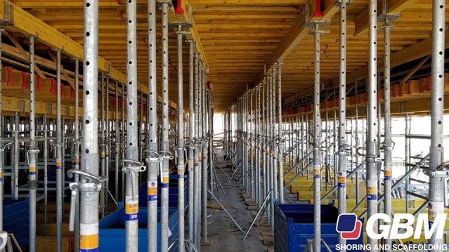
When it comes to constructing a slab, the standard procedure occurs through a system consisting of a continuous intrados surface of the slab obtained by means of a formwork made up of a wooden board; they are transversely sustained using wooden beams with a I-shaped section with variable height.
This system of beams is in turn borne by beams arranged longitudinally with respect to the panels, which rest on the supports consisting of the post shores (classes B - D - E).
The beams are generally laid on the post shore using a special component such as fork; a steel tripod stand is used with the aim of stabilising the entire system and allowing a quick, effective and safe release of the post shores.
As concerns the project, below are the distances to be established:
- The centre-to-centre distances between the transversal beams (1);
- The centre-to-centre distances between the longitudinal beams (2);
- The distances between the post shores (3).
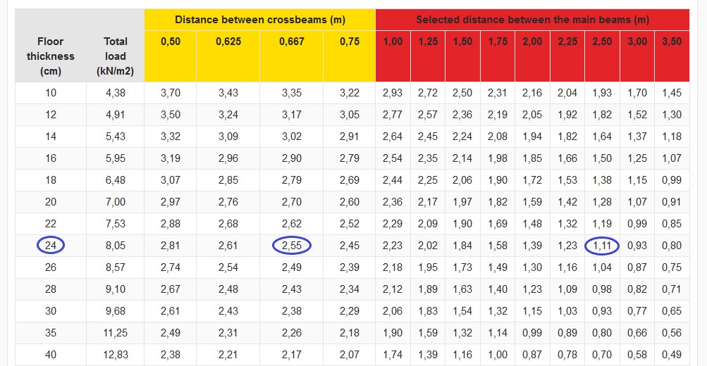
The table 1 below shows the standard distances as well as the general loads of the slab as a function of its thickness (IMPORTANTE: WARNING: When executing a project, this value must be calculated by a technician). In the example below, we will show how to calculate the right distances (1) and (3), starting from a distance (2) of our choice.
How do I determine the classes of the post shores to be used correctly?
The following must be verified in order to establish whether the class and the model of the post shore is functional to the execution of the work at hand: choosing a general class of post shore
C (ultimate load on post shore) < R (characteristic design strength)
with C given by the sum of the following values:
- Specific weight of the boards;
- Specific weight of the wood beams (transversal plus longitudinal);
- Specific weight of the chosen post shore;
- Concrete load;
- Moving load.
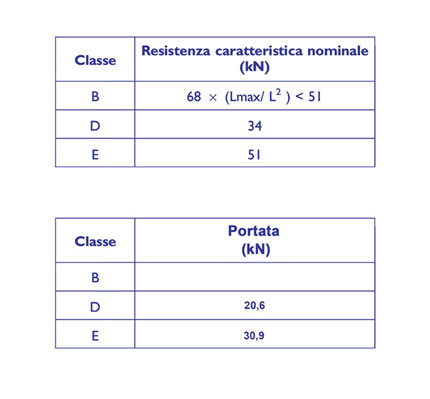
NB:R is calculated using the formulae present in table 2 as a function of the extension lengths of the chosen post shore and the height of the slab to be constructed.
How many post shores do I need to sustain my slab?
Upon establishing the centre-to-centre distances between the beams, the maximum distances allowed between the post shores, and the class/model of the post shores to be used, the number of post shores required will be simply obtainable based on the surface of the slab that they are designated to sustain.
How to read the tables – a practical example
Below is an example with remarks for the utmost illustration of the operations to be carried out step by step.
1. consider the thickness line of the chosen slab (e.g. 0.24 m).
2. decide a distance of the secondary beams, which will be our distance (2) for example 0.667 m in the columns with yellow header;
3. intersect the chosen line and column, this will allow to obtain the value of 2.55 metres;
4. retrieve our distance of the primary beams. To do this, we shall take the value just obtained, 2.55 metres, and find the value nearest thereto by rounding down, 2.50 metres in our case, from among the red boxes of the table. This will be our distance (1);
5. intersect the chosen line and the new column, this will allow to obtain the value of 1.11 metres, which is our distance (3).
Thus, we have the three distances: the centre-to-centre distance between the main beams 2.50 metres, obtained from the table; centre-to-centre distance between the secondary beams 0.667 metres chosen by us from among the available ones; distance between the post shores 1.11 metres obtained from the table.
Now, we want to establish whether a given type of post shore can be used or not. For example, let us select a class B, model B40 post shore (extension between 2.5 and 4.0 metres) with h extension equal to 2.8 metres between the underlying slab and the slab to be obtained in the formwork.
We will have the following data:
C= 32.55 kN; load resulting from design calculations including safety factor 1.5 – see NTC18 (Italian Technical Construction Regulations based on European Union regulations) – example data obtained from table 3.
R= 68x4.0/2.8² = 34.69 kN (Data calculated using the special formula found in table 2).
Given that 32.29 kN < 34.69 kN, the chosen post shore is deemed perfectly verified. Were this not the case, the class of the post shore should have increased verifying it as done previously.
NB: the formula above allowed us to verify whether each post shore compliant with class B40 requirements can bear the required load. The characteristic strength of 34.69 kN corresponds to a 21.02 kN capacity. GBM B40 post shores have superior characteristic strength (37.62 kN) and capacity (22.8 kN) with respect to the those required.
Reference tables
TABLE 1

TABLE 2

TABLE 3 - REFERENCE CALCULATIONS
Specific weight of the boards: 0,125 x 1,11 x 2,5 = 0,347 kN
Specific weight of the wood beams: 0,05 x (1,11 + (2,5 x 2)) = 0,306 kN
Post shore weight = 0,24 kN
Concrete load = 25 x 0,24 x 1,11 x 2,5 = 16,65 kN
Moving load (CNR 10027/85) = 1,5 x 1,11 x 2,5 = 4,16 kN
TOTAL = (0,347+0,306+0,24+16,65+4,16) x 1,5 = 32,55 kN
Last Update:
News

BAUMA 2025 - 7-13 APRIL 2025

GBM's shipbuilding scaffoldings

Post shores required to sustain a slab: guidelines on how to establish distances, classes and quantities.
GBM Contacts: info, prices & quotes
Would you like further information on GBM products? Ask anything!
 Italiano
 English
 Deutsch
 Français
 Português
 Polski
 Български
 Română
 Español
 Русский
 Српски
 Hrvatski
 Slovenski
 Shqip
Shqip Magyar
 English (US)